Optimal Instrument Panel
Home
Youtube-Channel
About
Shop
Good panel layout
Panel Layout
Gliding differs from normal aviation in some key areas. We are very reliant on looking out to find our way forward and find our next climb. Our main instrument is our eyes, senses and experience. While an engine pilot is very reliant on keeping his engine going(temps, RPM, fuel etc) we are reliant on keeping our eyes out of the cockpit to keep going.
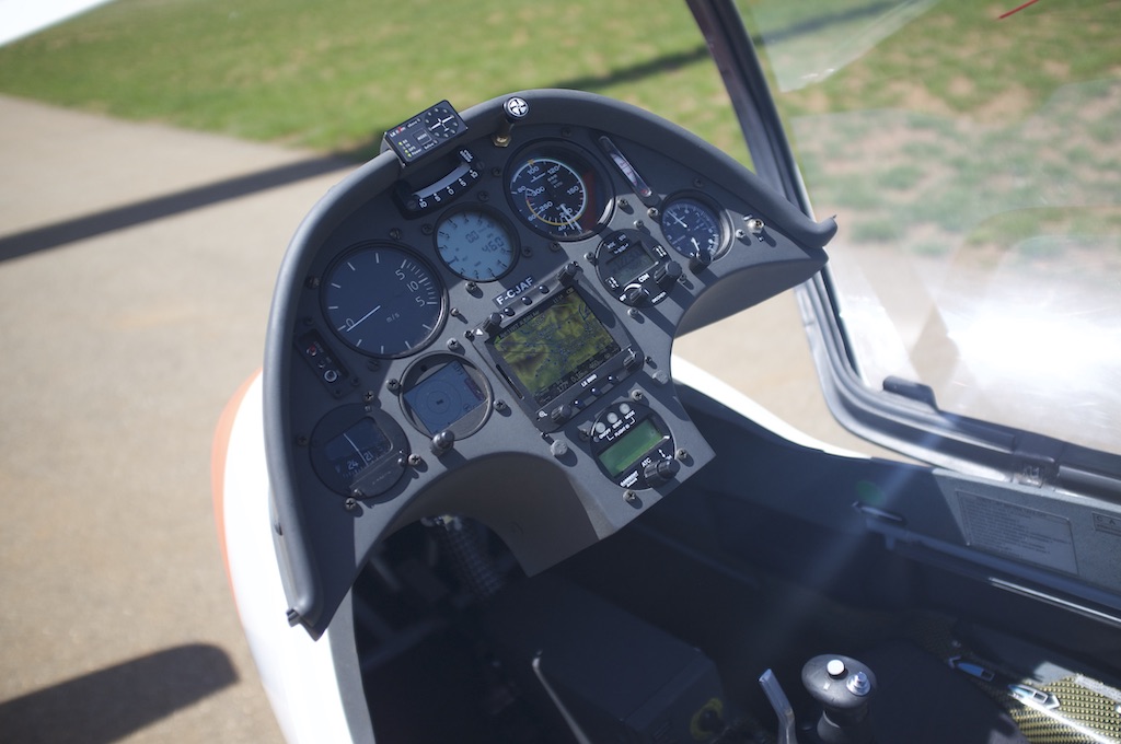
With this in mind we want a panel which can be read fast and easily. Look at this panel(same as above):
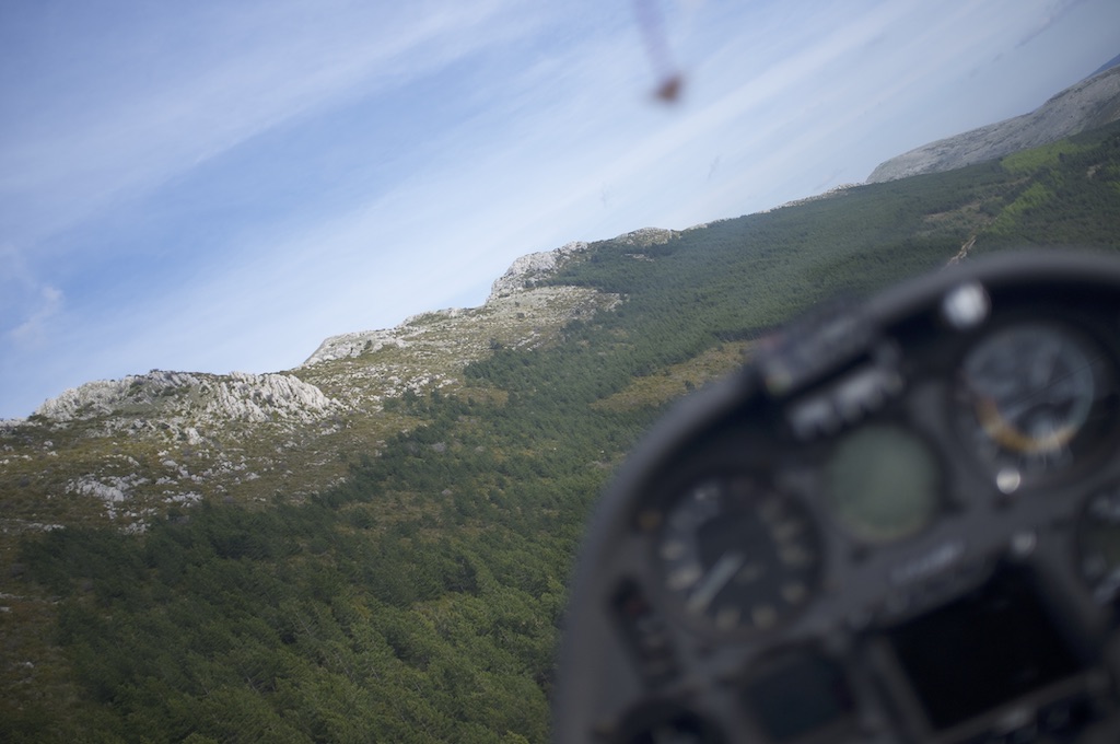
Flight in the French alps. Note the glide computer is OFF
As can be seen the 80mm variometer is easily readable without even having to focus on it. It is even possible to focus your eyes on one of the mountain tops and still be able to see the needle with your peripheral vision.
Second test, look up from your computer screen and look at some object around 5m(or more) away. Then, look back at your computer screen 'here' and then back at the object. This kind of transition(far away - close - far away) takes more than one second for a normal person. This is because your eyes needs to move, refocus, brain to register what it sees and also adjust the iris for different light.
With this in mind we want to have an instrument panel which can be roughly interpreted without focusing our eyes, minimal eye movement and instruments which requires less interpretation.
With the above information we can divid the instrument panel into three zones like this:
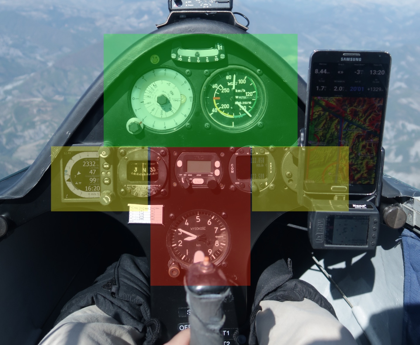
The green zone is for instrument which are often used. This area is the easiest to see with your peripheral vision and also requires less eye movement. The yellow area requires more eye movement and may also have darker light which requires the iris to readjust. The red area is the worst with long eye movements(maybe even head movement) and also readjust the iris for darker light. You can also see that part of the red area might be obstructed by the stick.
Instruments
Instruments classically comes in two sizes: 57mm and 80mm. From my own experience 57mm should only be used if there is no room for 80mm. With the above considerations the top part of the panel should have an 80mm air speed indicator, 80mm variometer and the simple FLARM display. The yellow area is a good place for radio/altimeter. Fuses, ON/OFF switches etc can be put in the red zone behind the stick. Then we arrive at the glid computer, where should it go? Let's talk a bit more about this.
The glide computer
Since the introduction of PDAs, around the millennial shift, we have seen big screens occupy more and more of our instrument panels. It's not uncommon to see pilots use several screens. The common norm nowadays is to fit the biggest screen possible and push the important instruments to the sides and reduced to 57mm. The big benefit of the screens is the display of the moving map, where you can graphically see your location relative to the task and airspace. I think the screens should be used with care since they can bring a lot of extra head-down time in the cockpit. All the vast amount of data that can be displayed are more likely to confuse rather than help in your flying. Limit yourself to the 5-8 most useful info-boxes and no more. Put the info-boxes high up on the screen to be closer to the green zone.
The modern day PDAs (smartphones) can be mounted on the side of the cockpit, in the yellow zone ,and is as such a better option. After flying with all types my experience is much more in favour of the side mounted PDA with touch screen. It's easy on the eyes and quick to use. A good example is TP move in an AAT area, this is much faster to do on a PDA type rather than panel mounted screen. On top of this you can program/prepare your task comfortable in the shade/briefing room rather than bending your back over the glider on the grid.
One Last Thing
It's not only important to have a good layout of the panel but also have correct and accurate information from the instruments. I've done some research on leakages in connections this year and found that the common PVC tube connections to the instruments often leak. To have a reliably tight connection there have to be a fresh piece of PVC tube, pulled all the way on the connection and also a spring loaded clamp holding the tube in place. Only one single disconnection will deform the PVC tube enough to, in most cases, cause a leak.
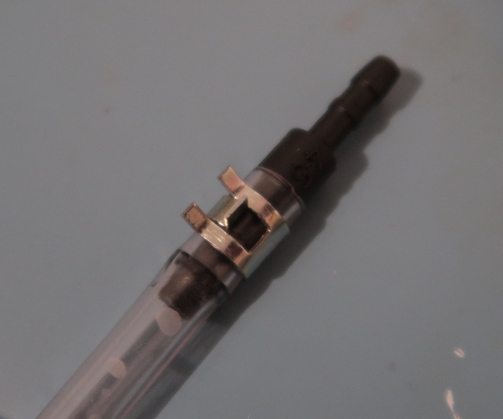
Correct hose connection
last update: 14 December 2020
Support me
I build and maintain this site to help you. I do it in my spare time and it's not free.
I DON'T WANT ADVERTISEMENT on this site. Help me to help you:
Buy me a beer!
© 2018 Niklas Löfgren
|